To fully describe the wavefunction, even when we treat the propagation of light through the scalar wave equation, having the intensity profile is not enough. A scalar wavefunction is defined by two parameters of intensity and phase. While the intensity characterizes the amplitude of the wavefunction, phase is an additional degree of freedom which controls the propagation of the light beam. Strategically phase modulation can change the wavefunction and lead to new applications of light.
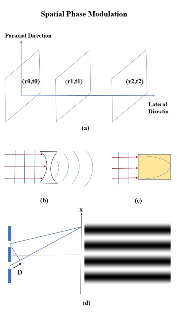
The phase of the light beam changes as a function of both distance (from the source to the screen) and time. As a result, there are pages of constant phase along the propagation direction. These pages, characterized by a constant distance (r) and time (t), are called phase-fronts. As the light propagates both of these parameters undergo variations. Therefore, this spatiotemporal function of the phase is named as dynamical phase. The spatial part is ruled by wave vector (k) defined by the wavelength (or spatial frequency). The temporal part is controlled by spontaneous frequency (w) which defines the speed by which the wave envelope propagates. If both of these factors remain constant, the phase fronts would be flat surfaces along the propagation direction (as depicted in Figure (a)). This type of wavefunction in which the phase varies with a constant rate is called plane wave. Synthesizing the phase of the light beam by engineering each of these parameters results in exploring new features of the wavefunction. The refractive index is the most usual element for modulating the phase. Because the refractive index causes a variation in the speed of light, any changes in this element affects the spatial phase; This is the strategy that is commonly used in fabricating lenses. While in traditional lenses, the thickness of the lens is modulated (Figure (b)), in the so-called graded index lens (Figure (c)) the refractive index is changed gradually throughout the structure according to a defined function.
In both kind of lenses, different points on the incident plane wave experience various speed due to the difference in the refractive index and, as a result, the emerging wave front exhibits a kind of sphericity. Another simple way to change the spatial part of the dynamical phase is to directly varying the pathlength of the light beam. This tactic was used in the well-known Young’s Double-slits experiment. In his set-up (Figure (d)), the pathlength of the secondary waves (waves appeared in front of the slits) to the point of observation are different. Consequently, there is a phase difference which causes the interference effects. The observed bright and dark fringes – as displayed in the right side of the figure – are the result of this spatial phase modulation; As if to say, the phase differences causes intensity variation.
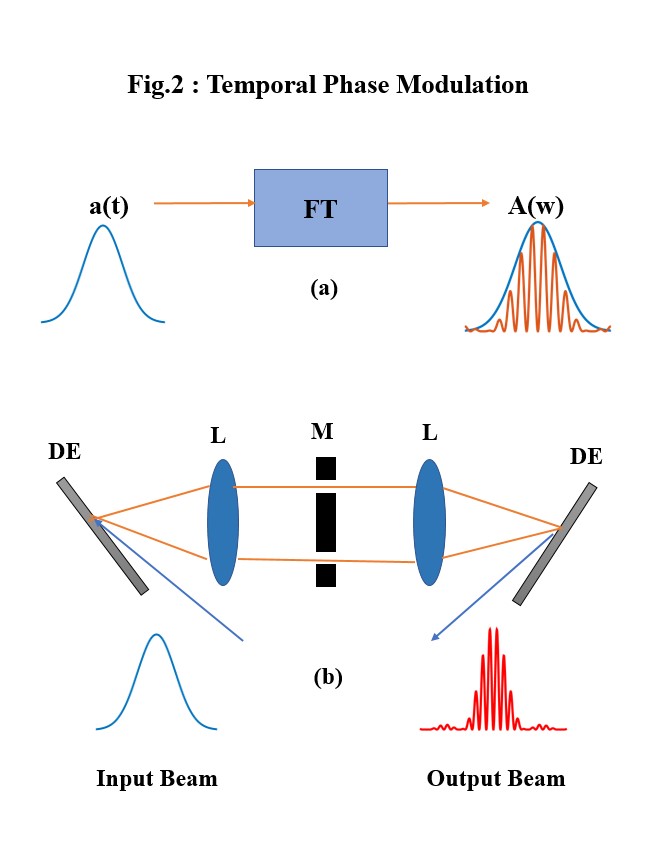
An analog of the Young’s interference experiment is a well-known technique for shaping the pulse (spectrum) in time domain. A beam, as mentioned above, propagates with a spontaneous frequency defining its temporal dynamical phase. However, any beam spectrum in time domain is a superposition of various frequencies. This superposition is known as Fourier Transformation (FT); A well-defined function which allows us to superpose various pulses with different frequencies in frequency domain to produce a pulse with a central frequency in time domain, or vice versa (shown in Fig.2a). As can be seen, the temporal amplitude of the pulse, a(t), is an envelop for the superposed pulses in frequency domain, A(w). Practically, each pulse can be decomposed into individual frequencies by a diffractive optical element like a grating (DE). Then a similar concept to the Young’s interference experiment can be applied to select some of the spectral frequencies. The interference of selected frequencies yield an optical tone burst (a well-defined sequence of pulses out of an envelope).
A process of producing a beat pattern by interfering two selected frequencies is shown in Figure2.b. The mask (M) is acting as Young’s double slits which can be generally designed for a desired spectral phase. The lenses (L) are the practical elements of Fourier transformation; The first lens is to transform the input diffracted temporal pulse (Input beam) into frequency domain to be shaped by the mask. The selected frequencies can posses various phase differences, induced by the mask, to produce different shapes of the beam pattern. The second lens combine the selected shaped frequencies and transform them again into time domain. Here, the final beam pattern (output beam) is simulated by interfering of two selected frequencies with a phase difference of pi. This technique, known as pulse shaping, can be applied for producing different patterns by shaping both amplitude and phase.
